Nissan Maxima Lower Control Arm Bushing Change Tutorial
Recently I noticed that my 1991 Nissan Maxima was pulling to the right. I took it to the tire shop for an alignment and the tech pointed out that my passenger side lower control arm front bushing was shot. He said he could align the car to prevent tire wear but it would continue to pull to the right because of the bad bushing. He also said that a new pair of control arms and the labor to do the job would be about $600. That did not make me happy so the first thing I did was go online and start looking to see how much a new set of control arms would be. From Courtesy Nissan they were $330 a pair plus shipping. Non-OEM controls arms could be had for $115 plus shipping. But I got to thinking and wondered if just the bushings could be replaced. It's not like the big hunks of metal were worn out, just the little rubber piece. So I started researching that and found that they could be replaced, but with more work involved. According to Matt Blehm the front bushings for a 2nd generation Maxima and the rear bushings for the 3rd generation Maxima could be used. However you would need a shop press to get the new front bushings in. Alternatively you could buy the 4th generation bushing kit from Energy Suspension. These were made of polyurethane and could be installed without a press. I went this route and found the cheapest price at Autozone for $34.99. They come in both red or black but I recommend the black because they are impregnated with graphite while the red are not. The part number for the black is 7.3111g. I want to note that when you read about front bushings and rear bushings this refers to the bushings on the front lower control arm. These have nothing to do with the rear suspension components of the vehicle.
Let me say that this was probably the worst job I have ever tackled on this car and that includes changing the timing belt, twice. It wouldn't be bad except nothing goes like it is supposed to. The inner bushing sleeve will be frozen onto the shaft. Also, the outer bushing sleeve will be frozen into the control arm. If not for those two things this would be an easy job. My thanks go to Matt Blehm and Greeny for their tutorials. Matt gets credit for his initial work and research as well as a more technical how to while Greeny gets props for having photos and a real world solution to removing the frozen sleeve. These two guides along with a Hayne's manual made this possible. I recommend reviewing both of the online tutorials and your own manual if you have one. Click on the thumbnails below to open full resolution images in a new window.
UPDATE: Today I got the courage to do the driver's side bushings. This went much smoother because the front bushing was not frozen to the shaft. This made getting the lower control arm out a piece of cake. I also didn't have to work on getting the frozen metal sleeve off of the shaft. This time around the entire job took four hours instead of two days (however many hours that was).
If there are any parts that can be improved or if you have any suggestions please let me know.
Other Nissan Maxima Tutorials:
Nissan Maxima Fuel Injector Change Tutorial
Nissan Maxima Timing Belt Change Tutorial
Nissan Maxima Digital Dash HUD Tutorial
Disclaimer: Use these directions only as a guide and at your own risk. You're responsible for any damage you do to the vehicle so BE CAREFUL. Your vehicle may in fact have slightly different methods so use common sense if the directions don't match what you see. The demo vehicle being shown is a 1991 Nissan Maxima SE with the VG30E engine and an automatic transmission. Bushings will vary within the 3rd generation by year, engine and transmission type. The tutorial was done on the passenger side of the vehicle.
Tools needed
- Socket set
- 14mm socket
- 17mm socket
- 22mm socket (I used a 7/8")
- 27mm socket
- 14mm wrench
- Breaker bar (recommended)
- 1/8"-1/4" drill bit
- Power drill
- Floor jack and stands
- Torque wrench
- Dremel type rotary tool with cut off discs
- Blow torch (like a Bernz-o-matic)
- Puller (you can get one from most auto supply "loan a tool" programs)
- Cold chisel (I used a long, thick shaft screwdriver)
- Hacksaw
- Hammer
- Bigger hammer
Vehicle prep
- Put the car in neutral and apply the parking brake
- Loosen the lug nuts on both front wheels (if doing both sides)
- Chock the rear wheels
- Jack up the car and place jack stands on both sides
- Remove the front wheel(s) (if you're doing both and KNOW you will have time to finish)
- Remove the inner fender splash guard (plastic clips). Mine was already removed and never put back so I don't have a picture of that.

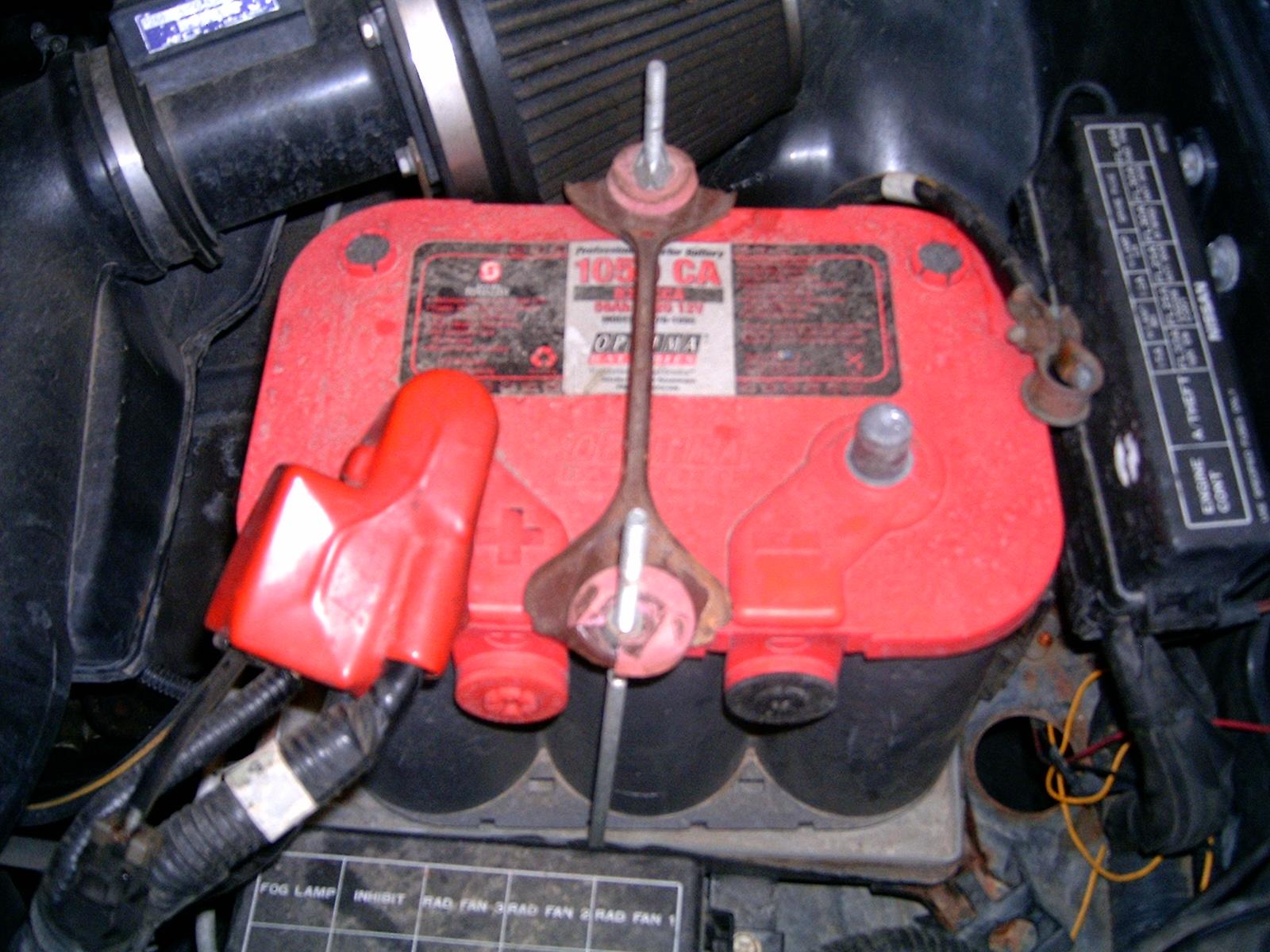
- Disconnect the negative battery terminal (10mm bolt)
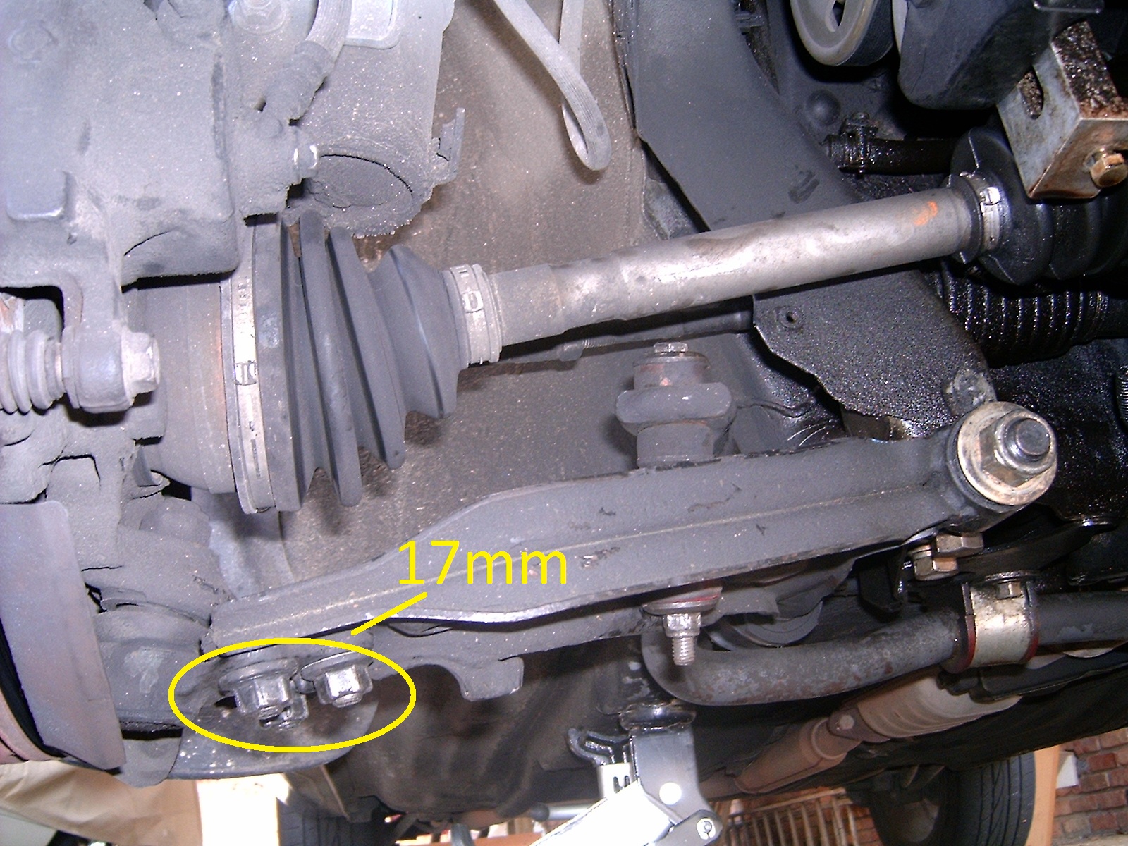
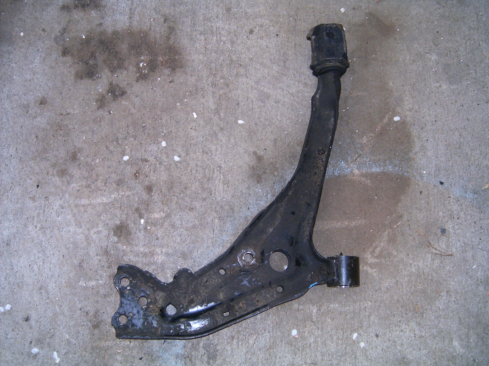
- Unbolt the three 17mm nuts from the ball joint (they're in a triangle pattern). Remove the three bolts from the ball joint. They're attached together on the top side so they have to come out as a unit. Give them a little tap with the hammer from the bottom to pop them up. (Greeny's tutorial says to remove the top nut from the ball joint but I recommend the three lower nuts as does Matt Blehm and Hayne's). Note that the ball joint goes under the lower control arm. When re-assembling I wasted 10 minutes trying to figure out why the fit was wrong because I had the ball joint on top. The photos below are of the passenger side lower control arm with the photo being taken from the front of the car (you're looking towards the back).
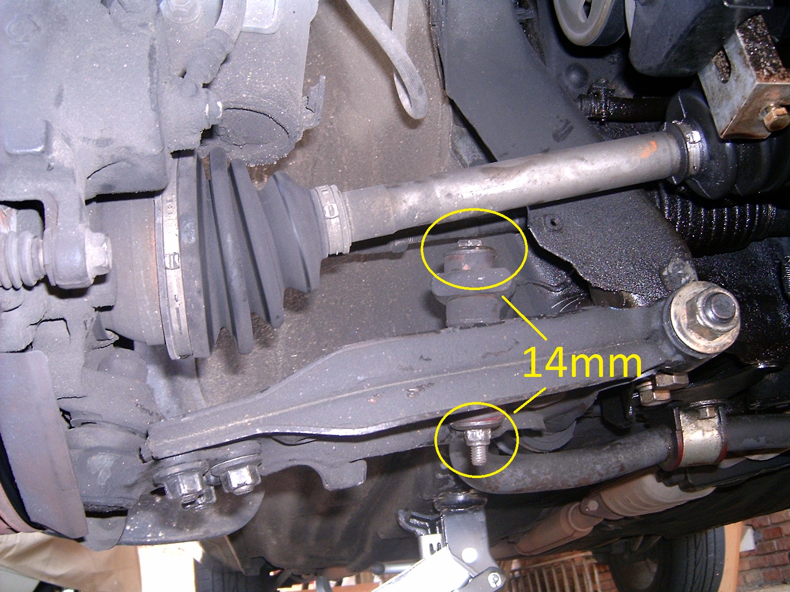
- Unbolt the 14mm nut from the bottom of the front sway bar end link and pull the bolt and assembly out of the lower control arm. You will need to put a 14mm wrench on the bottom due to the length of the bolt (or have a deep well socket). I have a Suspension Techniques sway bar set so your disassembly may be different. Make note of how everything goes back together. If you only do one side at a time you'll have a reference on the other side.
- Now get out the 27mm socket and remove the nut from the front bushing assembly.

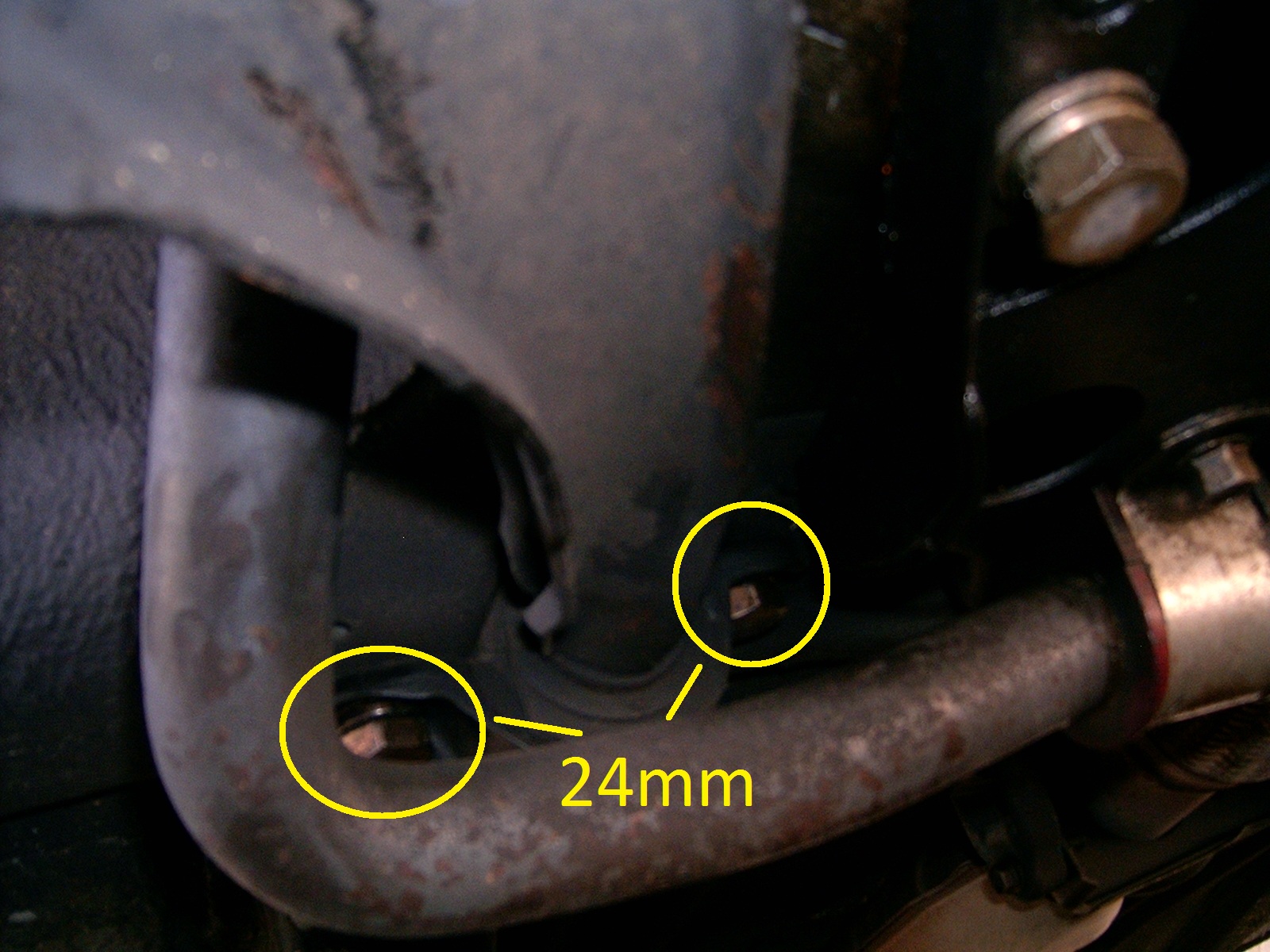
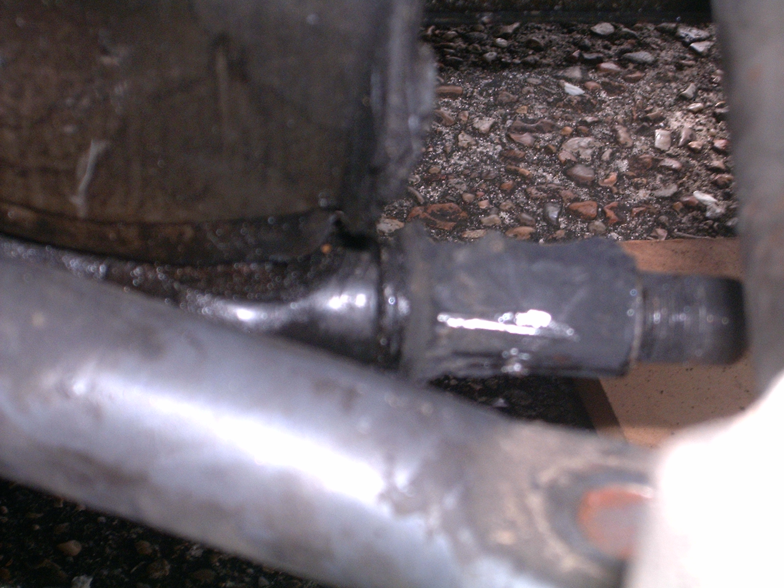
- Use a 22mm (or 7/8") socket (pic mistakenly labeled 24mm) and remove the two bolts from the bracket that holds up the rear of the lower control arm. There is a large rubber bushing between the bracket and the vehicle.
- Now move the ball joint out of the way and twist the control arm about the front bushing (the shaft that remains after you have removed the 27mm nut). If everything comes out then consider buying a lottery ticket because you are lucky today. Make sure the rear bushing is not being bound up by the front sway bar, especially if you have the thicker Suspension Techniques set. If the control arm remains in place, buckle up.
- Matt Blehm recommends using a puller to get the lower control arm off. That didn't work for me at all. Since the inner bushing sleeve is frozen to the shaft and the outer bushing sleeve is frozen to the control arm you're basically trying to tear the thick rubber bushing apart. I found there is just too much force holding the rubber together to make that work.

- After that fail I tried out the method shown by Greeny in his tutorial. Bust out the drill and bits and make a series of holes in the rubber bushing. Since the inner and outer sleeves are metal they will protect the control arm and shaft from getting gouged by the drill bit. Do not go too small on the bit or you won't remove enough material but don't go too big or you'll be fighting the bushing too much. All you want to do is weaken the bushing so the amount of rubber holding it in is much smaller and therefore weaker. I didn't take a photo of this but you can find it in the pictures on Greeny's tutorial. Once you have removed enough of the rubber you can twist the control arm off the shaft. Again, make sure the rear bushing isn't holding the assembly in place.
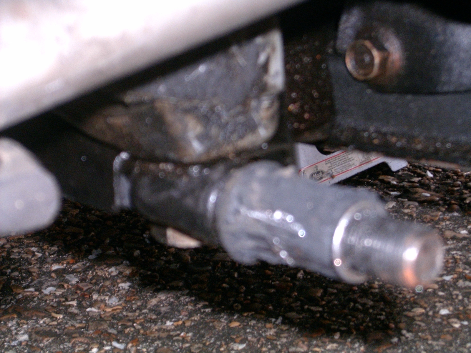
This leaves you with a shaft still frozen to the rubber covered sleeve. We'll deal with that later.
You're also left with the now removed control arm which still has the rubber covered outer bushing sleeve frozen in. We'll deal with that now.
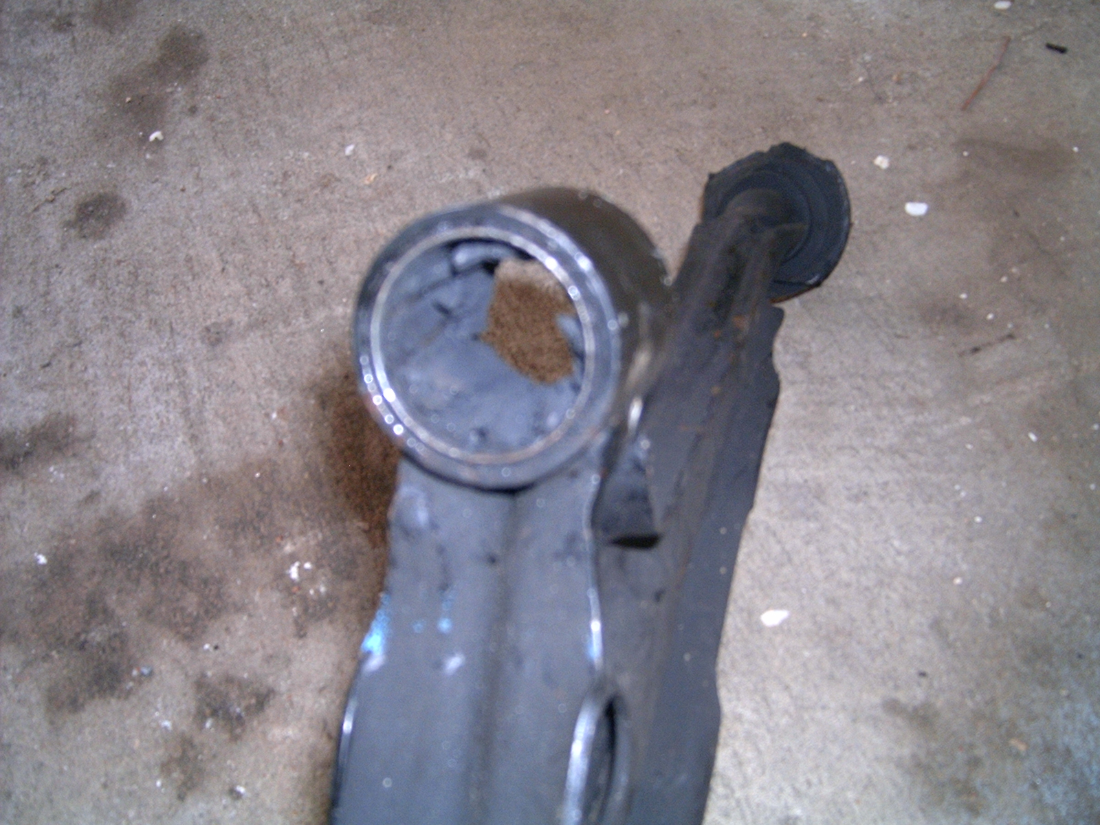
- For this part we return to the method proposed by Matt Blehm. Break out the blow torch and burn the rubber out of the control arm. Place the lower control arm in a vice with the bushing end facing you for easy access (as seen above). Then fire up the torch and burn the rubber out of the bottom section of the outer sleeve. The rubber will catch fire but shouldn't burn uncontrollably. Eventually it will die out and leave some hardened pieces of grey/white rubber. You can push or dig these out with a screwdriver. All you're doing is clearing a section of the metal sleeve so you can cut it. If you are uncomfortable with the burning method you should be able to cut through the rubber with just a hacksaw. Allow the sleeve and bushing to cool before proceeding.
- UPDATE: If the control arm came out and the sleeve was not frozen to the shaft (it remains inside the bushing) then you will need to get it out. I used the drill bit method to "hog out" the rubber until the inner sleeve could be removed. Once that was out I used the blow torch to burn the rubber out of the bottom section. This is the only part where rubber really needs to be removed as it is where the two hacksaw cuts will be made.
- UPDATE: If the control arm came out and the sleeve was not frozen to the shaft (it remains inside the bushing) then you will need to get it out. I used the drill bit method to "hog out" the rubber until the inner sleeve could be removed. Once that was out I used the blow torch to burn the rubber out of the bottom section. This is the only part where rubber really needs to be removed as it is where the two hacksaw cuts will be made.
- The next step is more of the Matt Blehm method. Disassemble your hacksaw and push the blade through the bushing opening. Then reassemble the hacksaw with the blade inside the bushing. Now make two cuts about 1/4" apart in the bottom of the channel (where you burned out the rubber). Use caution as you approach the bottom of the cut to avoid cutting into the control arm itself. It's best to stop a little short as the next step will probably remove the remaining metal.
- Once the cuts are made use a cold chisel (that's a stout metal chisel, not sharp, that you can beat on) to peel up the thin piece of metal between the two cuts. I don't have a cold chisel and I was only able to make one cut before my hacksaw broke. What I did was take a sturdy punch and peeled up the metal on either side of the single cut. I did this from both sides of the bushing opening. It took a long time but eventually the sleeve came out. I then used a sanding drum on a Dremel to polish up the rusty surface and smooth out any gouges made in the control arm metal. I found out later this probably wasn't necessary as the Energy Suspension bushings do not have an outer metal sleeve.
- UPDATE: On the second control arm I was able to make two cuts. I did not go all of the way through the sleeve but the metal still peeled up nicely. Once most of the inner section has peeled up the sleeve will probably come right out as you keep hammering.


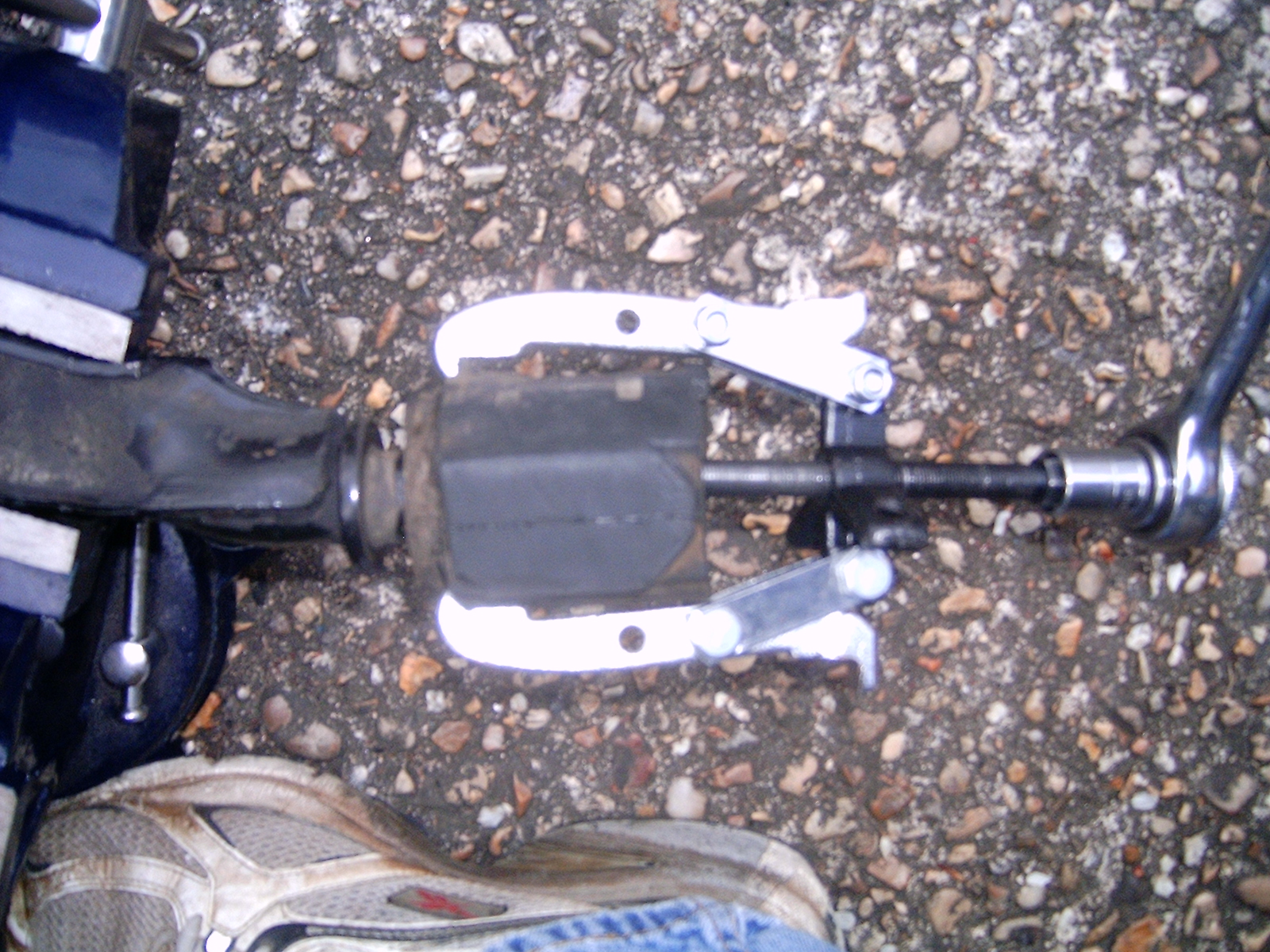
- To remove the rear bushing I found it necessary to use a two jaw puller. It came off pretty easily with this method.
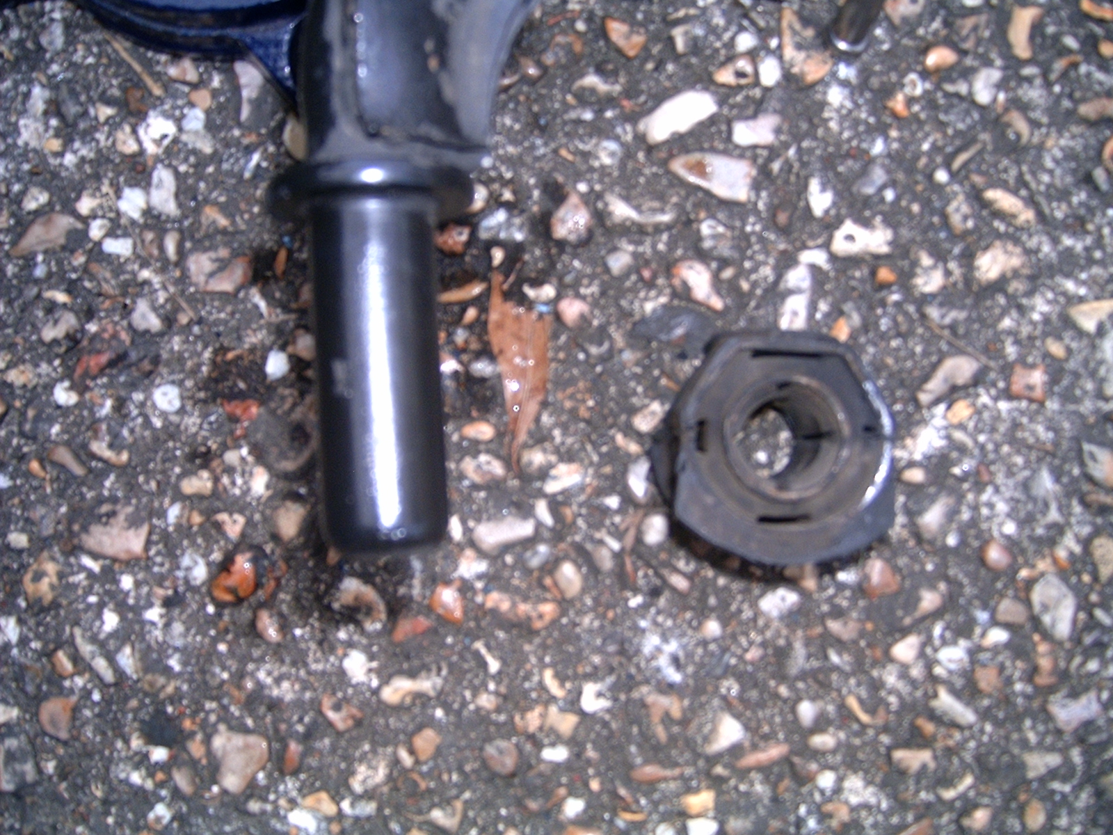
- Now we can return to the vehicle to remove the inner sleeve from the shaft. Here we use the Greeny method again (Matt Blehm's tutorial does not cover how to remove a frozen inner sleeve). Using a Dremel and a cutting disc make a channel along the length of the sleeve. I did this from the side of the sleeve that was accessible from the wheel side of the vehicle. This allows you to get the necessary leverage and angles to remove the sleeve in a later step. As before, be careful that you don't unnecessarily cut into the shaft. If you cut most of the way through and weaken the sleeve metal you should have done enough to remove it.
- Once you have a good cut into the sleeve you can use a long, sturdy screwdriver to get the sleeve loosened. Place the screwdriver blade into the cut at a downward angle (45 degrees or thereabout). Then use a hammer to hit the screwdriver and drive the blade into the sleeve. You want to direct the force downward and not into the shaft. The goal is to twist the sleeve so it breaks loose and can be removed. Greeny recommends splitting the sleeve along the seam which may work but I was concerned about putting too much force into the shaft. By angling the force and directing into the sleeve most of the force does not go into the shaft. Once the sleeve is removed use some emery cloth or a Dremel with a sanding attachment to polish up the shaft.
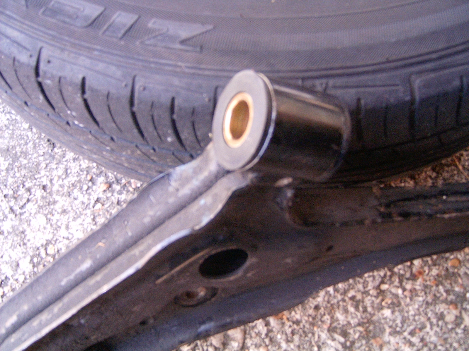
- Now it's time to install our new bushings onto the lower control arm. The front bushings from Energy Suspension go right in. Place the supplied inner sleeve inside one of the bushings and push the bushing into the control arm. Take the other bushing and press it in from the other side over the sleeve. The lip on the bushings goes to the outside and shouldn't fit any other way.
- The rear bushing requires some fitting. And by "fitting" I mean some serious cutting into a thick piece of stiff polyurethane. Using the tools I had at hand I figured I could use a chop saw with a metal cutting wheel to remove the necessary material. I put the bushing in the freezer overnight to make it even stiffer. I don't know how effective that really was but it made me feel better. The chop saw worked fine using care when cutting. It did make a mess of the saw as melted polyurethane stuck to and then hardened in place. A hacksaw may have worked too but mine was broken as mentioned before. On the Energy Suspension rear bushing you need to remove some of the flat end and at least one angle cut. Matt Blehm has a good picture of that though there are no dimensions in the picture. I found that if you cut right above the lip on the flat side (removing the lip in the process) that's about the right amount of material. Basically you can use the original bushing from the car as a guide. I also found you only need to cut an angle into one side. That's the side that will face the middle of the car on the passenger side and the outside of the car on the driver's side. At least that's how it is on my automatic. The cut is to clear a protrusion in the floor pan. Even after cutting the Energy Suspension rear bushing is a little too thick for the bracket. However I can tell you from experience that it will squeeze in once the bolts are installed. Push the newly sized rear bushing onto the shaft. Use a little dish soap on the shaft so the bushing slides on more easily.
- Now it's time for reassembly. Thread the rear of the control arm past the sway bar while at the same time placing the front bushings over the shaft. There are two large washers supplied with the kit and I installed one on each side of the front bushing during assembly. Make sure the washers slide over the shaft without binding. On the driver's side I had to use a Dremel tool and a sanding drum to remove some metal from the inner diameter of the washers. Test that both fit before proceeding. Place one washer on the shaft before putting the control arm back in.

- LOOSELY attach the rear bushing 22mm bolts, the 27mm front bushing nut, 14mm front sway bar bolt/nut and the 17mm ball joint trio. Remember that the control arm goes on top of the ball joint. Once everything is where it should be fully tighten the rear bushing 22mm bolts and 14mm front sway bar bolt/nut combination. Firm up but do not tighten the three 17mm ball joint nuts or the 27mm front bushing nut.
- Install the front wheel(s) and tighten the lug nuts. Lower the car to the ground and torque the lug nuts to the proper setting (my car calls for about 80 ft-lbs). Now with the wheels on the ground torque the ball joint trio and the front bushing nut. My manual says about 70 ft-lbs for each. Depending on the length of your torque wrench you may not be able to get the proper leverage while the car is on the ground. I drove my car up on ramps which gave me enough room while still keeping pressure on the wheels and suspension.